
Neodymium Magnet Assembly Handling: Prevent Chips, Attraction and Orientation Errors
Neodymium Magnet Assembly Handling
A neodymium magnet can be made to the correct grade, size and coating yet still be damaged or installed incorrectly during the next assembly step. The key risks are usually practical: parts attracting together unexpectedly, coated edges contacting hard surfaces, a polarity-sensitive magnet being turned the wrong way, or mixed lots reaching the same workstation. A simple handling plan gives the production team a controlled way to prevent these avoidable problems.
The right method depends on magnet strength, part geometry, coating, quantity per station and the final assembly. The aim is not to add unnecessary handling steps. It is to define a stable part condition from receiving through the first-piece check and routine assembly.

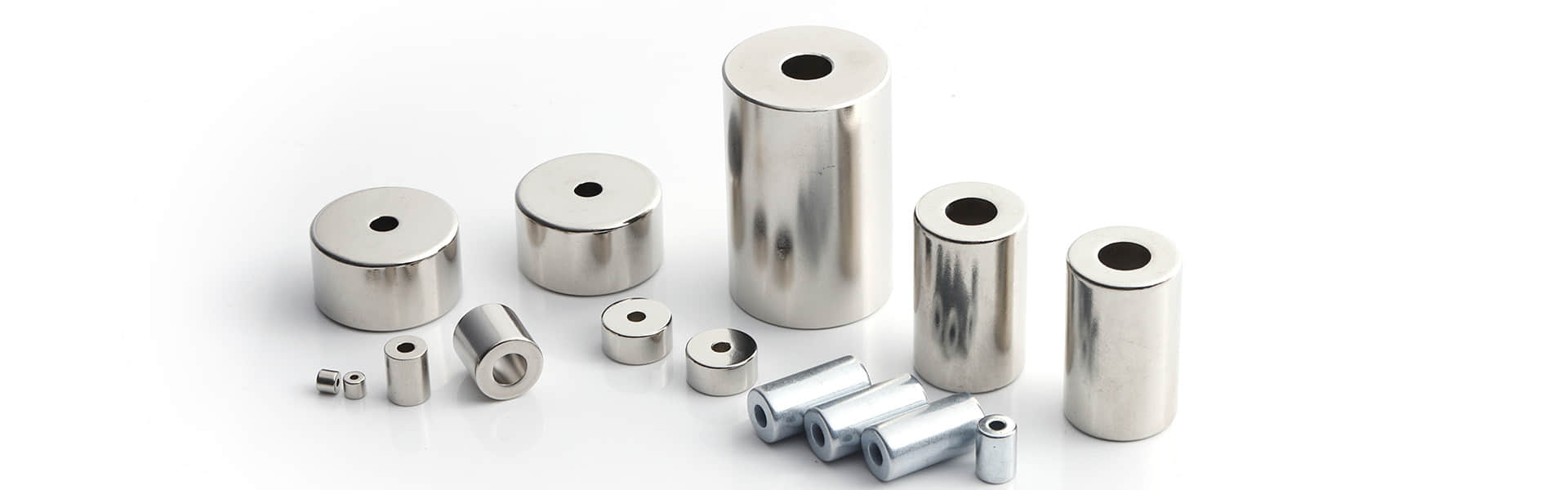
Figure 1. Real neodymium magnets in several shapes: handling method should match the part geometry and the assembly task.
Define the safe assembly state first
Before a magnet is placed at a workstation, decide how it should arrive and how it should be presented to the operator or automated fixture. A part supplied as a loose single piece may need a different approach from a controlled stack, a tray of separated parts or a matched set. Describe the condition in the work instruction so purchasing, receiving, production and quality teams use the same expectation.
Assembly state | What to define |
Single parts | Whether each magnet arrives in an individual pocket, sleeve or other controlled position that prevents unintended contact. |
Controlled stacks | The maximum stack arrangement, separation method and safe way to remove one piece without twisting or snapping parts together. |
Matched sets | How matched parts are grouped, labelled and kept together when the final product needs a defined pair or sequence. |
Workstation presentation | The tray, non-magnetic locator or pick position that gives the same orientation to every part at the point of assembly. |
Return material | How unused pieces are re-identified and returned without mixing them with another lot, polarity group or inspection status. |
Protect coatings and brittle edges from sudden contact
Sintered neodymium magnets are hard, but they can chip if they collide with another magnet, a steel tool or a rigid edge. Coatings can also be marked by uncontrolled contact. Use a suitable non-magnetic tray, separator, sleeve or locating feature for the actual part. The handling approach should let the part be placed and removed in a controlled direction instead of allowing magnets to jump together.
· Keep loose steel tools, fasteners and ferrous debris away from the active handling area unless they are part of the approved fixture.
· Use separators and trays sized for the real profile so parts cannot roll, nest or slide into one another during normal movement.
· Review any handling or fixture change with a representative magnet before the change is released to routine production.

Figure 2. Real bored cylinder magnets: trays and locating features should support the actual profile without allowing parts to collide or mix.
Control orientation only where it affects function
Not every magnet needs a visible polarity mark at the assembly station. For a simple holding application, the working face may be obvious from the part shape or fixture. For a sensor, paired latch, motor segment or another directional assembly, the work instruction should state the required reference face, pole orientation or assembly position. A simple fixture key, labelled tray or first-piece reference can be more reliable than relying on operator memory.
Requirement | Practical control to consider |
Working face must be outward | Use a fixture that accepts the magnet in one approved position, or show the face clearly on the approved assembly reference. |
Polarity-sensitive assembly | Define the North or South reference when necessary and use an agreed check method before the assembly is closed or bonded. |
Matched pair or array | Keep the sequence, tray position or group identifier linked to the inspection or sorting record. |
No orientation requirement | State that the part is non-directional for the assembly step so unnecessary marking and checking are not introduced. |
Use a first-piece check before routine assembly
The first completed assembly is the practical time to confirm that the chosen handling method supports the product. Check the part number, visual condition, orientation where relevant, fixture fit and the finished assembly result. If an adhesive, potting process or pressed fit makes later correction difficult, confirm the reference and placement before that irreversible step begins.

Figure 3. Real countersunk block magnets: part position and working face should be confirmed before fastening or another irreversible assembly step.
What to include in the production pack
Production pack item | Why it matters |
Approved part reference | Connects the workstation to the correct drawing, revision, grade, coating and profile. |
Handling state | Tells receiving and production whether material must stay separated, stacked, paired or positioned in a specific tray. |
Orientation reference | Prevents a directional part from being installed incorrectly when the application requires a defined working face or pole. |
First-piece record | Captures the accepted handling, fixture and inspection result before routine production begins. |
Lot and status identification | Keeps inspected, matched or hold material distinguishable throughout the assembly process. |
Conclusion
Reliable neodymium magnet assembly handling begins with a defined part condition, not a last-minute reaction at the workstation. State how the magnets will be separated, presented and identified; add orientation control only where the product needs it; and use a first-piece check to confirm the real fixture and assembly method. This protects the magnet and makes the production process easier to repeat.