
Neodymium Magnet Pull Force: Compare Holding Tests Correctly
Neodymium Magnet Pull Force
Neodymium magnet pull force is often requested as a quick way to compare holding ability. The number is useful only when the test arrangement is clear. A magnet does not produce one universal pull-force result because the measured outcome changes with the steel target, contact area, air gap, direction of pull and fixture used for the test. The right question is therefore not only what pull force was recorded, but how it was recorded.
This guide helps buyers and project teams define a comparable test request. It does not replace responsible application design, safety review or testing of the completed assembly, especially where people, moving equipment or critical retention is involved.
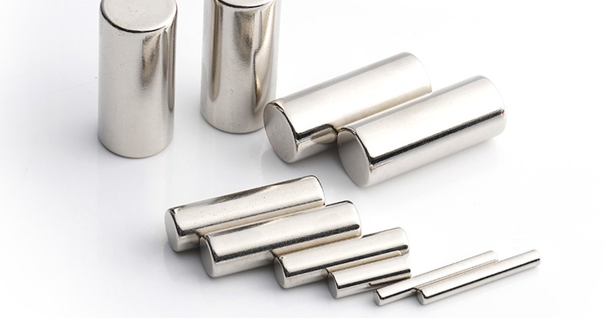
Figure 1. Real cylindrical neodymium magnets: a pull-force figure only has meaning when it is linked to a stated test arrangement.
Treat pull force as a test result
A published or measured pull force describes the force observed in a particular setup. It should be read together with the part reference and test conditions. If two suppliers report values using different steel targets, gaps or directions, the figures may not be directly comparable even if the magnets look similar or carry the same grade label.
Test condition | Why it changes the result |
Magnet part definition | Shape, dimensions, material grade, coating and magnetization arrangement identify the exact item being tested. |
Target material | The target steel type, thickness, surface condition and flatness can affect the magnetic circuit and measured holding result. |
Contact condition | Paint, plating, dirt, protective film, roughness or a deliberate spacer can create an air gap between magnet and target. |
Pull direction | Direct separation, sliding or a mixed load condition place different demands on the same assembly. |
Fixture and measurement method | The way the magnet, target and force gauge are held can influence alignment and the recorded peak value. |
Define the steel target and contact condition
The mating steel belongs in the pull-force request. State the material if known, its thickness, the target area available for contact and any coating or finish on the surface. Also identify whether the magnet is expected to contact the steel directly or through paint, an adhesive layer, a protective film, a housing wall or another spacer. A small unrecorded gap can make a bench result unsuitable for comparing the finished assembly.
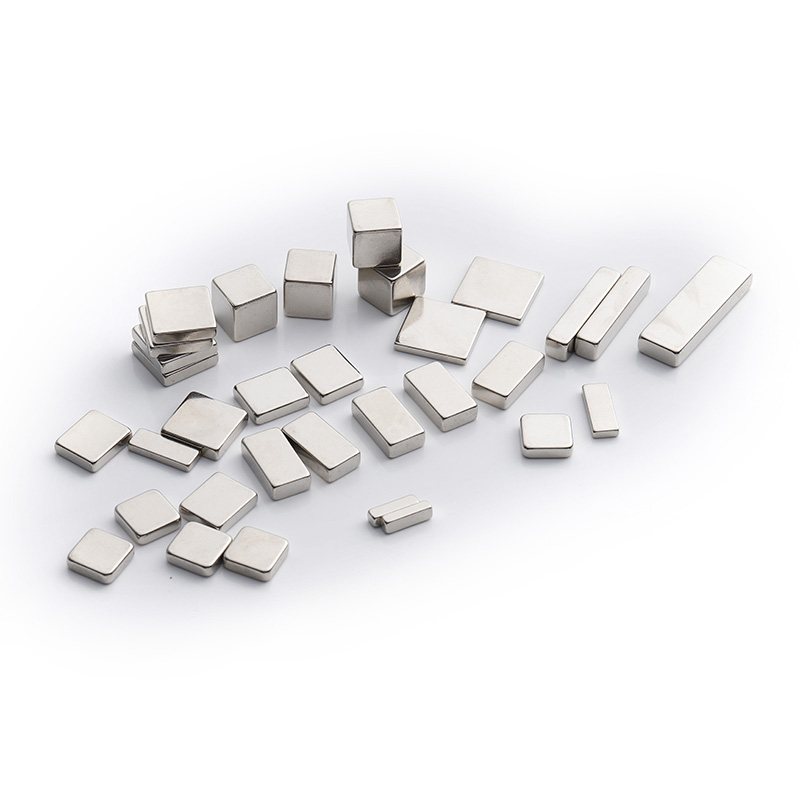
Figure 2. Real nickel-plated block magnets: the available contact face and the mating steel condition should be stated with any holding test request.
State in the test request | Example of the required detail |
Target steel | Material description, thickness, surface finish and the contact area available to the magnet. |
Contact stack | Direct contact or every layer between the magnet and steel, including paint, film, adhesive or a known spacer. |
Magnet orientation | Which face meets the target and how the magnet is located during the measurement. |
Pull direction | Whether the test measures direct separation, shear resistance or another defined loading direction. |
Acceptance basis | The agreed sample, test setup, number of observations and how the result will be reported or compared. |
Keep the load direction realistic
A magnet pulled straight away from a flat steel target is not the same situation as a magnet resisting a sliding force, vibration, a peeling action or an off-axis load. Describe the actual force direction and how the component is retained in the final assembly. If the product includes a housing, adhesive, fastener or mechanical stop, that assembly detail should be evaluated as part of the application rather than inferred from a direct pull test alone.
· Identify the direction, point of application and any expected movement or vibration in the final use.
· Separate magnetic holding from mechanical retention provided by a housing, fastener, adhesive or stop.
· Do not use a direct pull figure as a generic guarantee for shear, dynamic or safety-critical conditions.
Compare values only like for like
The most reliable comparison uses the same part definition and the same test setup. Make a simple comparison record rather than copying a force number from a product page into an assembly specification. This lets the buyer see whether a difference is related to the magnet, the target, the gap or the method used to measure it.
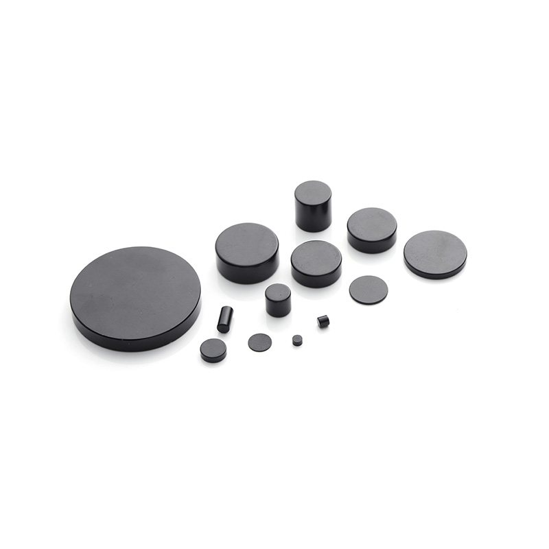
Figure 3. Real black epoxy-coated disc magnets: surface finish and contact stack should remain part of the recorded test condition.
Comparison point | Check before using the result |
Part reference | Confirm the dimensions, grade, coating and magnetization arrangement represent the same finished magnet. |
Test target | Confirm the steel material, thickness, contact area and surface condition are equivalent. |
Gap and contact layers | Confirm whether the same paint, film, adhesive, housing wall or spacer is present in both tests. |
Load condition | Confirm direct pull, shear or other direction and fixture arrangement are matched. |
Reporting basis | Confirm the unit, sample reference, test method description and any agreed acceptance rule are recorded. |
Use samples to confirm the assembly
For a new project, the final check should use the intended magnet, mating part and assembly condition. Review the location, contact surfaces, operating temperature, loading direction and the way the component is handled in use. Record the test arrangement and sample revision so a later production order refers to the same condition. This is more useful than relying on an isolated catalogue value when the application includes a gap, finish, housing or moving load.
Include in the sample review | Why it helps |
Finished magnet reference | Links the sample to the approved drawing, grade, coating and magnetization requirement. |
Mating component | Tests the actual target material, geometry, finish and contact area intended for the assembly. |
Fixture and load direction | Makes the setup repeatable enough for the project team to understand what the result represents. |
Application conditions | Identifies project-specific temperature, movement, handling or exposure factors for responsible review. |
Recorded outcome | Creates a traceable record of the sample, setup and acceptance decision before production release. |
Conclusion
Neodymium magnet pull force is useful when it is treated as a defined test result. Specify the exact magnet, steel target, contact stack, air gap, pull direction and fixture before comparing any value. Then confirm the finished assembly with an appropriate sample review. This gives the buyer and supplier a clearer basis for discussing holding performance without turning one bench number into a generic promise.