
Neodymium Magnetization Direction: Axial, Diametrical, Radial and Multipole Guide
Neodymium Magnetization Direction: How to Specify Axial, Diametrical, Radial and Multipole Patterns
The same magnet grade and size can perform very differently when the pole orientation changes. This guide helps buyers and engineers specify the correct magnetization direction before sampling or mass production.
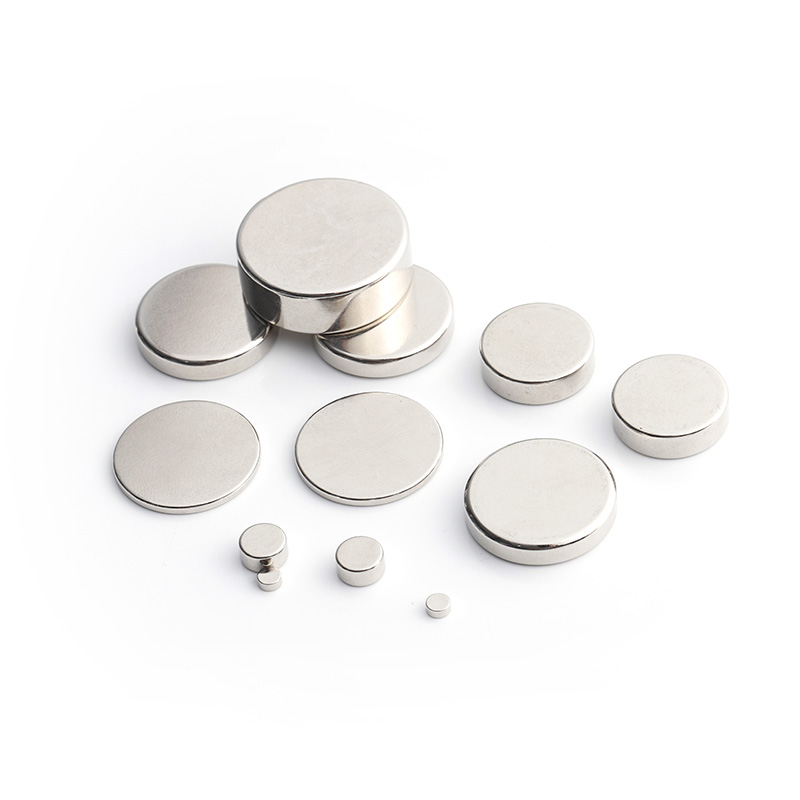
Choosing a neodymium magnet is not only about grade, size, coating and tolerance. Magnetization direction is equally important. It defines where the North and South poles are located and how the magnetic field works inside your final assembly.
If the magnetization direction is omitted from an RFQ, a supplier may assume a standard configuration. That can cause the wrong samples, poor sensor performance, unexpected pull force or an unusable motor assembly.
What is magnetization direction?
Magnetization direction describes the orientation of the magnetic poles in a permanent magnet. It affects the working surface of the magnet, magnetic-field distribution and interaction with nearby steel parts, sensors or other magnets.
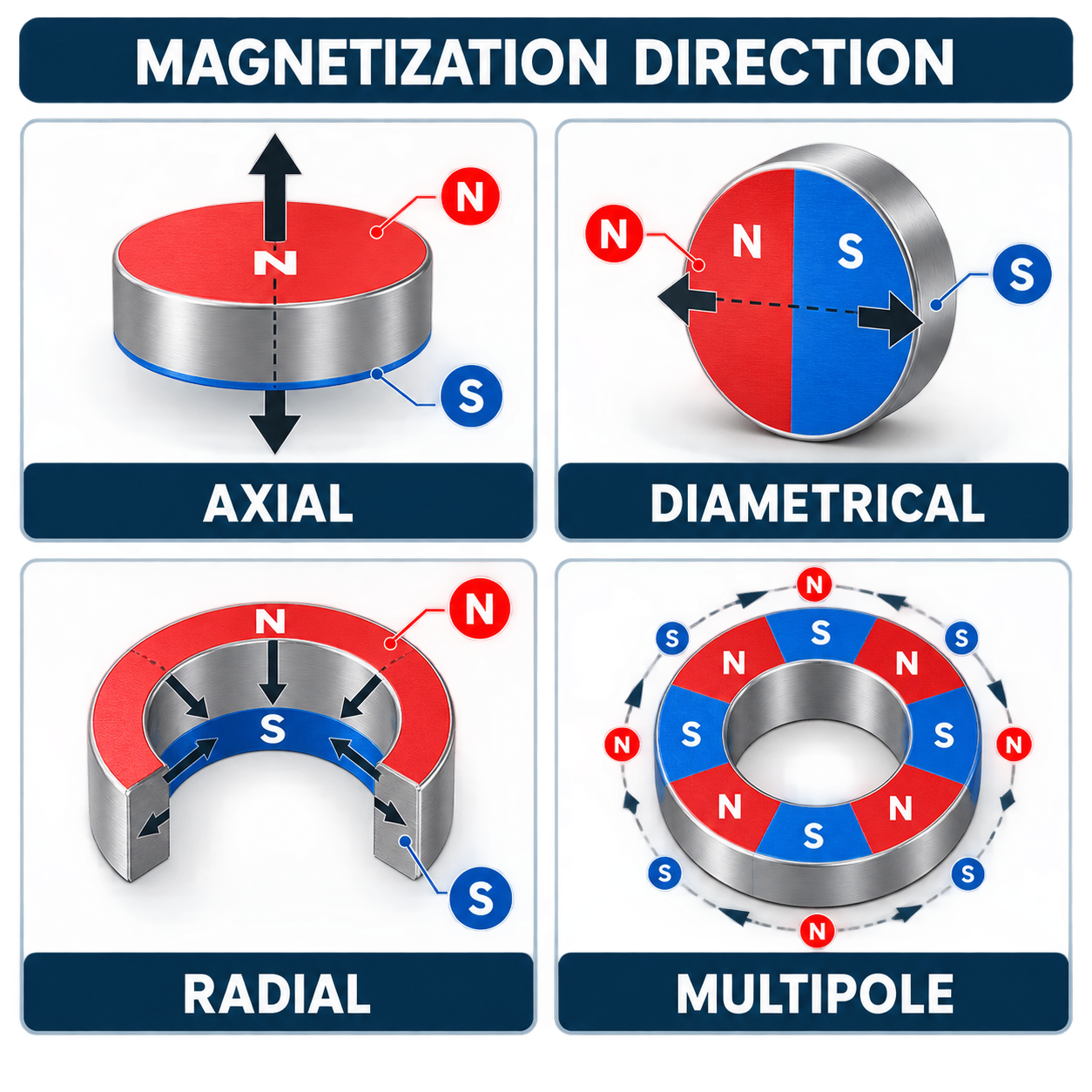
The four common configurations are shown below.
1. Axial magnetization
Axial magnetization is common for disc, cylinder and ring magnets. One flat face is North and the opposite flat face is South; the magnetic field runs through the thickness.
It is often suitable for direct holding, mounting, fixtures and pot-magnet assemblies. For a disc magnet, state the direction clearly, for example:
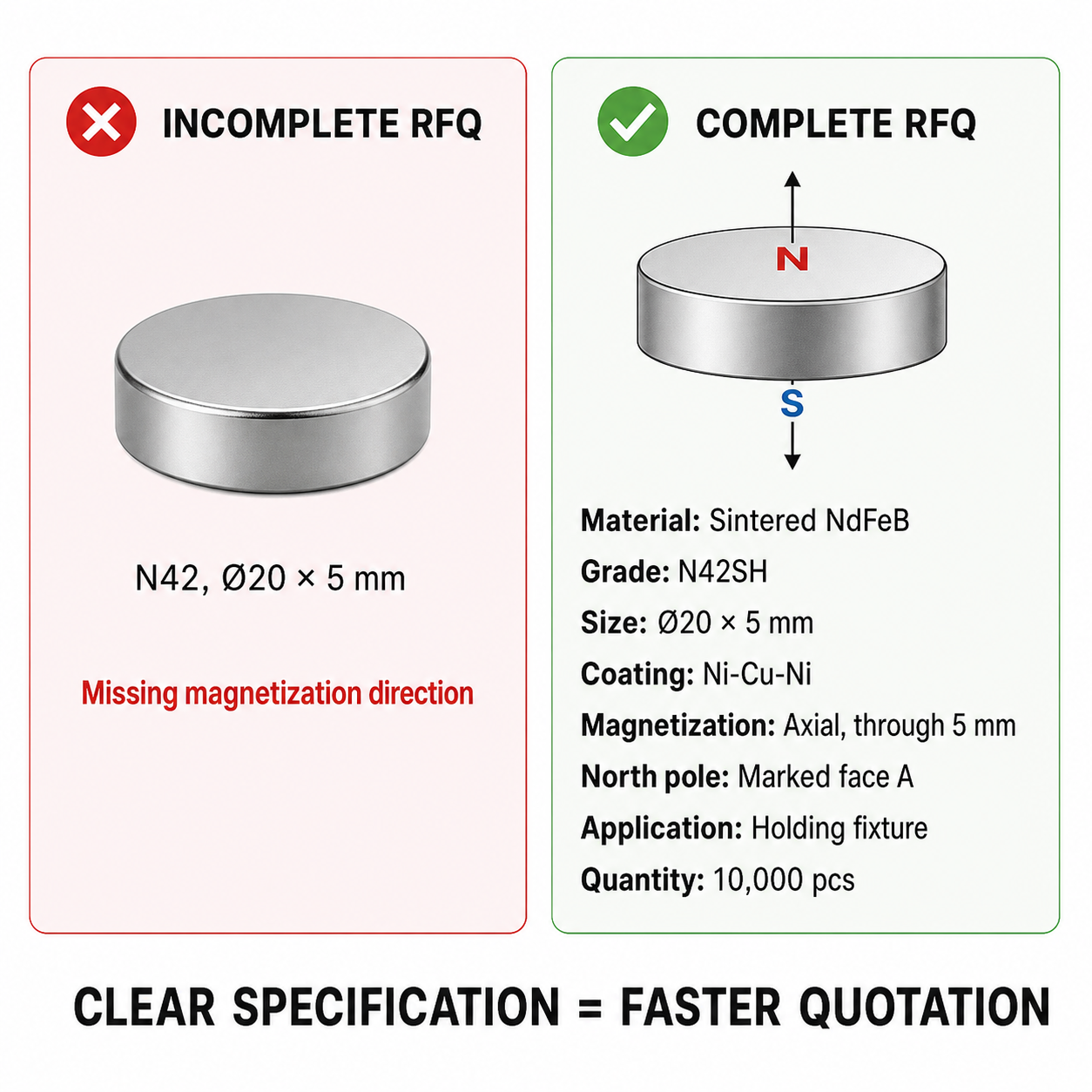
Magnetization: axial, through 5 mm thickness. North pole on marked face A.
This is more reliable than writing only “axial”, especially when the drawing contains several dimensions.
2. Diametrical magnetization
With diametrical magnetization, the North and South poles are on opposite curved sides of a cylinder or disc. The magnetic field runs across the diameter rather than through the flat faces.
This configuration is commonly considered for rotary sensors, encoders, angle measurement and some compact rotating assemblies. It is usually not the first choice for a simple holding application, because the useful magnetic field is concentrated at the sides rather than the flat contact face.
3. Radial magnetization
Radial magnetization is commonly specified for ring magnets, arc magnets and motor segments. Depending on the design, the inner diameter and outer diameter become opposite poles.
It can be appropriate for magnetic couplings, motors, generators and applications where flux must cross a circular air gap. For these parts, an assembly cross-section is often more useful than a dimension drawing alone.
4. Multipole magnetization
Multipole magnetization creates several alternating North and South poles around a ring or across a magnet surface. It is used when the application requires a controlled changing field, such as in encoders, speed sensors and selected motor systems.
For a multipole RFQ, include the pole count or pole pairs, pole pitch, pole sequence, reference point and inspection requirement. “Multipole ring magnet” alone is not a complete specification.
Choose the direction from the application—not from the magnet shape
Application requirement | Typical direction to evaluate | Information to confirm |
Direct pull or holding on a flat steel surface | Axial | Working face, air gap, test method |
Rotary angle sensing | Diametrical | Sensor position, shaft direction, pole orientation |
Motor, generator or magnetic coupling | Radial or multipole | Air gap, pole count, rotor geometry, temperature |
Encoder or speed sensing | Multipole | Pole pitch, reference point, measurement location |
The final choice depends on the magnetic circuit, available space, operating temperature and performance target. When in doubt, send the assembly drawing instead of guessing from a product photo.
Custom shapes need an assembly drawing
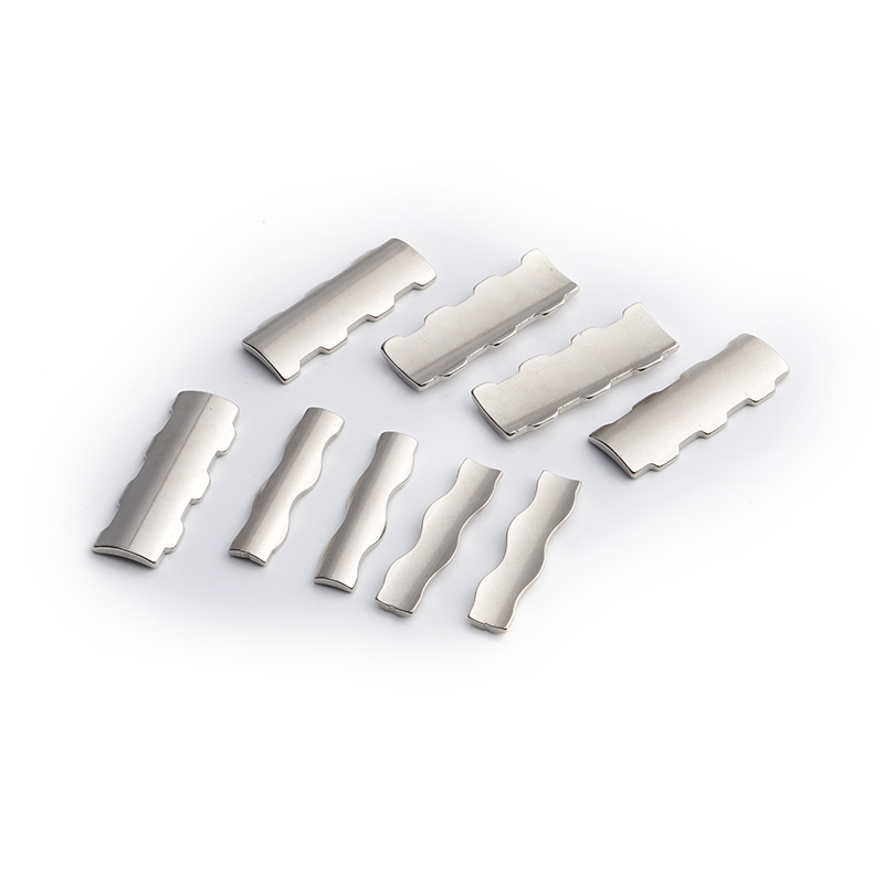
Arc, segment and other irregular magnets are often used in applications where magnetization direction is especially important. Their dimensions, curvature, pole arrangement and installation position must work together.
Avoid this common RFQ mistake
An RFQ such as N42, Ø20 × 5 mm tells the supplier the grade and size, but it does not identify the magnetization direction, pole reference, coating, quantity or use case.
The following example shows the level of information that helps a supplier review feasibility and quote efficiently.
What to include in a custom magnet RFQ
Please include the following whenever possible:
· Drawing, CAD file or clear dimension sketch
· Magnet shape and dimensions
· Material grade and maximum operating temperature
· Coating or surface-treatment requirement
· Magnetization direction and North-pole reference
· Pole count and pole pitch for multipole designs
· Tolerance and inspection requirements
· Application description and assembly drawing
· Sample quantity, mass-production quantity and destination port
Request a magnetization review
Xilai Technology supplies custom neodymium magnets and magnet assemblies. Send your drawing, application, required quantity and target delivery port for a feasibility review. If the magnetization direction is uncertain, we can review the working surface and assembly requirements with you before quotation and sampling.