
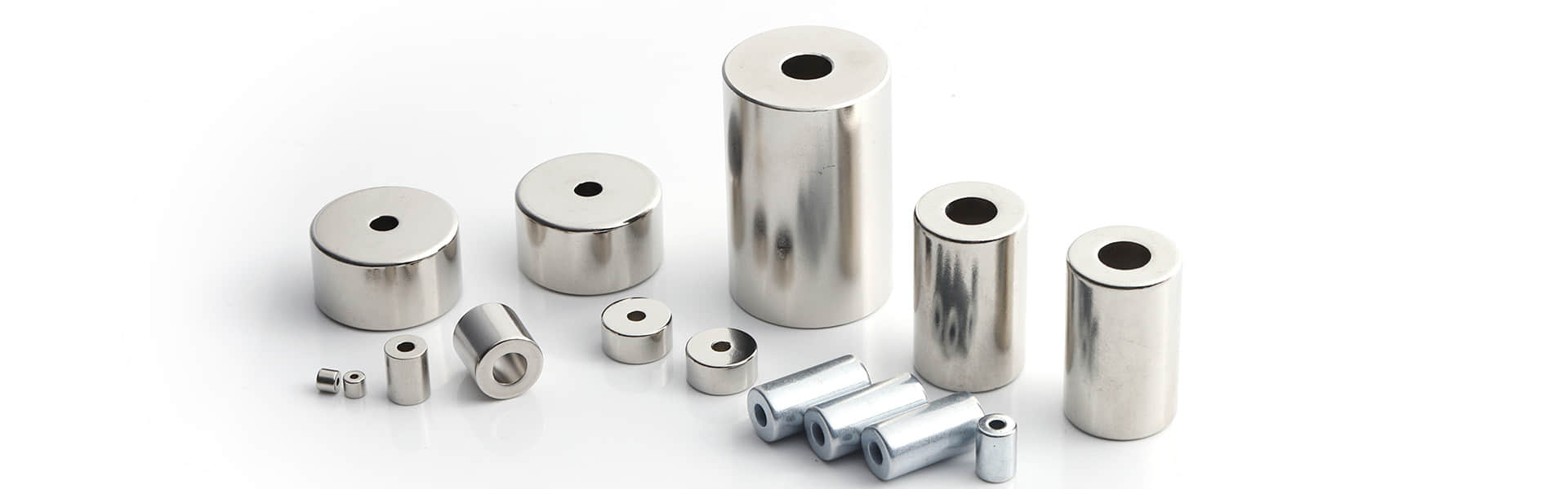
Neodymium Magnets in Industrial Automation: Sensors, Actuators, and Magnetic Grippers
Introduction
The modern factory floor is filled with robots, conveyors, and automated cells. Behind many of these movements and detections are neodymium magnets – often invisible but essential components.
Unlike EV motors (which use magnets for continuous rotation) or wind turbines (power generation), automation applications demand precision, repeatability, and reliability in small packages.
This guide covers three key automation applications:
Magnetic position sensors (Hall effect, reed switches)
Linear actuators (voice coil motors, magnetic slides)
Robotic grippers (magnetic end-effectors)
Part 1: Magnetic Position Sensors
Magnetic sensors are everywhere in automation: detecting cylinder position, measuring shaft rotation, or verifying part presence.
1.1 How Magnetic Sensors Work
A magnet is attached to the moving part. A sensor (Hall effect or reed switch) detects the magnetic field as the magnet approaches.
Common sensor-magnet configurations:
| Sensor Type | Magnet Requirement | Typical Gap | Output |
|---|---|---|---|
| Hall effect (linear) | Field strength varies with distance | 0-10 mm | Analog voltage |
| Hall effect (switching) | Minimum threshold field | 2-5 mm | On/off |
| Reed switch | Magnetic field closes contacts | 3-8 mm | Dry contact |
| Magnetoresistive (MR) | Small field changes | 0-5 mm | High precision |
1.2 Magnet Specification for Sensors
Unlike holding magnets (maximizing pull force), sensor magnets need stable field characteristics over temperature and time.
| Parameter | Requirement for Sensors | Why |
|---|---|---|
| Grade | N35 or N42 (not N52) | Higher grade = more thermal drift |
| Coating | Ni-Cu-Ni (standard) or epoxy | Epoxy for wet environments |
| Magnetization | Axial (through thickness) or diametrical | Depends on sensor orientation |
| Tolerance | ±0.05 mm | Critical for consistent switching point |
| Temperature stability | N35 (lowest drift) or N42SH (if hot) | Switch point shifts with temperature |
Real-world example: A pneumatic cylinder manufacturer uses a D6x4mm N35 axial magnet in the piston. The Hall sensor on the cylinder body detects the magnet at 5mm distance with ±0.5mm repeatability over -10°C to 60°C.
1.3 Common Sensor Magnet Shapes
| Shape | Typical Use | Magnetization Direction |
|---|---|---|
| Disc | Piston position, rotary encoder | Axial (through thickness) |
| Ring | Hollow shaft, through-hole mounting | Axial or diametrical |
| Block | Linear slide position | Through thickness |
| Cylinder | Rotary limit switch | Diametrical (across diameter) |
Selection tip: For ring magnets, specify ID tolerance carefully. A loose fit on the shaft causes inconsistent switching points.
Part 2: Linear Actuators (Voice Coil Motors)
Voice coil actuators (VCAs) use the interaction between a magnet and a coil to produce linear motion – like a speaker but for precise positioning.
2.1 Magnet Configuration in VCAs
Most VCAs use a moving coil design: the coil moves, the magnet is stationary. Or moving magnet: magnet moves, coil stationary.
| Configuration | Moving Part | Magnet Location | Best For |
|---|---|---|---|
| Moving coil | Coil | Fixed (magnet assembly) | High acceleration, low mass |
| Moving magnet | Magnet | Moving (attached to load) | No wires to moving part |
Magnet arrangement in a typical VCA:
A cylindrical magnet (or magnet stack) sits inside a steel housing. The coil surrounds the magnet. When current flows, the coil moves linearly.
2.2 Magnet Specifications for VCAs
| Parameter | Typical Value | Why |
|---|---|---|
| Grade | N42H or N42SH | High temperature from coil heating |
| Shape | Cylinder or segment | Radial magnetization |
| Coating | Ni-Cu-Ni | Dry environment (inside housing) |
| Magnetization | Radial (outer to inner diameter) | Field crosses the coil |
| Remanence consistency | ±3% maximum | Force consistency |
Radial magnetization challenge: Magnets with radial fields (north on OD, south on ID) are more expensive and have longer lead times than axial magnets. Many VCA designs use multiple arc segmentsassembled into a ring – each segment magnetized radially.
2.3 Real-World Example: Pick-and-Place Actuator
A pick-and-place machine uses a small VCA for fine Z-axis positioning. The actuator requires:
Stroke: 10 mm
Force: 5 N continuous
Response time: < 10 ms
Magnet specification used:
Type: N42SH radial ring (6 arc segments)
OD: 25 mm, ID: 15 mm, Height: 20 mm
Coating: Ni-Cu-Ni
Result: Achieved 6.2 N peak force, 8 ms settling time
Part 3: Magnetic Robotic Grippers
For handling ferrous parts (steel plates, iron castings, metal stampings), magnetic grippers are faster and simpler than mechanical or vacuum grippers.
3.1 Types of Magnetic Grippers
| Type | Magnet Type | On/Off Control | Best For |
|---|---|---|---|
| Permanent magnet (manual) | Neodymium + steel | Manual lever to switch | Simple, low cycle |
| Electro-permanent | Neodymium + Alnico + coil | Electric pulse to switch | Safe (no power needed to hold) |
| Electromagnet | Steel core + coil only | Continuous power to hold | High cycle, but fails if power lost |
Electro-permanent grippers are the industry standard for robotic handling. They use a combination of neodymium (high strength) and Alnico (switchable) magnets. A short electric pulse reverses the Alnico field, turning the gripper on or off. Once switched, no power is needed to hold – safe and energy-efficient.
3.2 Magnet Specifications for Electro-Permanent Grippers
| Component | Grade | Role |
|---|---|---|
| Main holding magnet | N42 or N45 | Provides majority of holding force |
| Switchable magnet | Alnico 5 or 8 | Changes polarity to turn on/off |
| Coil | Copper wire | Generates switching pulse |
Typical performance:
Holding force: 50-500 kg per gripper module
Switch time: 0.1-0.5 seconds
Power required (to switch): 50-200 W for 0.5 seconds
3.3 Real-World Example: Automotive Stamping Line
An automotive plant handles steel blanks (2m x 1.5m x 2mm thick) from a stack to a press. The previous vacuum gripper was slow and failed on oily surfaces.
Solution: Four electro-permanent gripper modules, each containing N45 neodymium magnets.
Results:
Cycle time reduced from 12 seconds to 6 seconds
No compressed air required (saved $15,000/year)
Zero dropped parts in 6 months
Gripper continues to hold even if power fails
Magnet specification for each module:
Type: N45 neodymium blocks, 50mm x 25mm x 10mm
Quantity: 8 blocks per module
Coating: Epoxy (to resist oil and coolant)
Holding force per module: 180 kg
Part 4: Design Guidelines for Automation Magnets
4.1 Material Selection Chart
| Application | Recommended Grade | Alternative | Notes |
|---|---|---|---|
| Hall sensor (room temp) | N35 | N42 | N35 has lower temp drift |
| Hall sensor (hot environment) | N35H or N38H | - | Maintains field at 100°C+ |
| VCA actuator (high cycle) | N42SH | N45SH | Higher grade = more force per size |
| Magnetic gripper (holding) | N45 or N48 | N52 | Balance of strength and cost |
| Reed switch trigger | N35 (small) | N42 | Reed switches need minimal field |
4.2 Magnetic Field Simulation
Before prototyping, engineers use FEA software (e.g., FEMM, Maxwell, JMAG) to simulate:
Field strength at sensor location
Force vs. position for actuators
Holding force vs. air gap for grippers
Common simulation inputs:
Magnet grade (Br, Hcj)
Magnet geometry
Steel housing properties
Air gap distance
Pro tip: Send your CAD model and performance targets to XiLaitech. We provide free magnetic simulation for automation projects.
4.3 Temperature and Aging
Neodymium magnets lose a small percentage of flux over time – called long-term irreversible loss.
| Operating Temp | Loss after 10 years (N42) | Recommended Action |
|---|---|---|
| 20°C | < 1% | Ignore |
| 60°C | 2-3% | Design with 5% safety margin |
| 100°C | 5-8% | Use H or SH grade |
| 120°C+ | > 10% | Use SH or UH grade |
For precision sensors (e.g., linear encoder with magnetic scale), specify low-temperature-coefficient grades or add temperature compensation in software.
Part 5: Case Study – Magnetic Linear Encoder
Application: High-precision XY positioning stage for semiconductor inspection.
Requirement: Position feedback with ±1 micron resolution, 50 mm travel.
Solution: Magnetic linear encoder using a magnetic scale (alternating north-south poles) and a magnetoresistive sensor.
Magnet specification:
Type: N42 neodymium magnetic tape (flexible)
Pole pitch: 2 mm (1 mm north, 1 mm south)
Length: 60 mm
Thickness: 1.5 mm
Backing: Steel backing to concentrate field
Results:
Achieved ±1 micron resolution
Robust against dust and oil (unlike optical encoders)
Lower cost than glass scale encoder
Operating temperature: 10-50°C
Supplier note: Flexible magnetic tape is cut to length and adhesively mounted. XiLaitech offers custom-pole magnetization for encoder applications.
Conclusion
Neodymium magnets enable three key automation technologies:
| Application | Key Magnet Requirement | Common Grades |
|---|---|---|
| Position sensors | Stable field over temperature | N35, N42 |
| Voice coil actuators | Radial magnetization, high Hcj | N42H, N42SH |
| Magnetic grippers | High holding force, switchable | N45, N48 |
For engineers and buyers: always specify grade, coating, magnetization direction, and temperature range. Automation magnets are small but critical – a 5% field variation can cause sensor failure or inconsistent gripping.
Need custom automation magnets? XiLaitech supplies sensor magnets, radial rings, and electro-permanent gripper components with full magnetic simulation support.