
Neodymium Ring Magnets for Shaft Assemblies: A Practical Specification Guide
Neodymium Ring Magnets for Shaft Assemblies
A neodymium ring magnet can be a compact part of a shaft assembly, but its hole, working face and surrounding components need to be considered together. The same ring may be used for position sensing, a magnetic coupling, a rotary feature or another defined function. A useful request describes what the magnet must do in the assembly before it asks for a grade or a nominal size.
This guide helps purchasing and engineering teams prepare clear information for supplier review. It does not replace the magnetic, mechanical or safety design needed for the final shaft assembly, especially where rotation, heat, high speed, vibration or critical performance is involved.
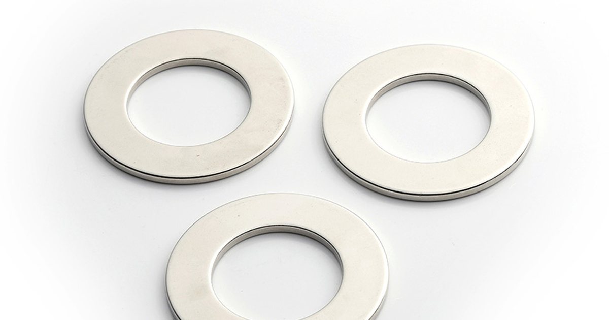
Figure 1. Real neodymium ring magnets: the hole and working faces should be defined in relation to the complete shaft assembly.
Start with the shaft assembly function
Before selecting a ring magnet, identify the role it performs after installation. Is it mounted to a shaft, retained by a hub, placed near a sensor, coupled across a gap or used with another magnetic component? Record the mating parts, rotation path, available space and the location where the magnetic effect is needed. This makes the drawing and sample discussion more useful than a request based only on a catalogue image.
Assembly question | What to clarify |
Magnet function | Whether the ring supports sensing, coupling, indexing, holding or another specific assembly task. |
Mounting position | Which shaft, hub, sleeve or locating feature controls the magnet position and which face is the functional reference. |
Motion and access | Whether the magnet is stationary or rotating, how it is installed and whether later removal or service is required. |
Adjacent components | Nearby steel, another magnet, a sensor, bearing, adhesive or non-magnetic spacer that can affect the final arrangement. |
Operating environment | Temperature, humidity, cleaning media, vibration and any other exposure that the project design must address. |
Define the ring from its finished mounting condition
A ring magnet is more than an outside diameter and a hole. The finished inner diameter should be connected to the real shaft or sleeve condition, while the outer diameter and thickness should be linked to the available envelope and the adjacent parts. Identify any chamfer, edge treatment, locating shoulder or bonded surface that affects assembly. Where a coating changes a critical fit, state whether the acceptance dimension applies to the finished coated part.
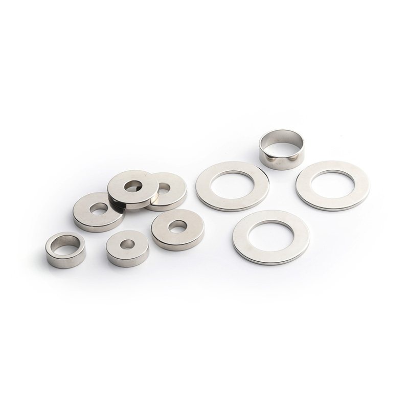
Figure 2. Real small ring magnets: finished inner diameter and locating surfaces should match the real mounting condition.
Connect magnetization to the working reference
The required magnetization must be specified in the context of the shaft assembly. For a ring, an axial, radial or multipole pattern may be considered depending on the intended magnetic circuit and function. The drawing or assembly note should identify the required direction, the working reference face or diameter and, where needed, the pole sequence or reference point. The supplier should not have to infer this from the ring shape alone.
Requirement to define | Why it matters in a shaft assembly |
Magnetization direction | Connects the pole arrangement with the intended sensing, coupling or working surface rather than a generic ring description. |
Reference face or diameter | Shows which face, inner surface or outer surface is related to the mating component or measurement point. |
Pole reference if needed | Supports correct installation where a sensor, paired magnet or indexed position depends on a defined pole location. |
Working gap | Records the designed separation from the sensor, steel component or paired magnetic part in the finished assembly. |
Validation method | Defines the functional check, fixture or assembly test needed to confirm the sample performs as expected. |
Review the working gap and nearby materials
The completed magnetic result depends on the complete arrangement, not only on the magnet. A small change in the gap, a steel retaining part, a changed spacer or a different sensor position can alter the result. Include a section view or assembly sketch showing the ring location and its neighbouring materials. For an application that needs a repeatable response, agree the representative assembly or fixture used for sample approval before production begins.
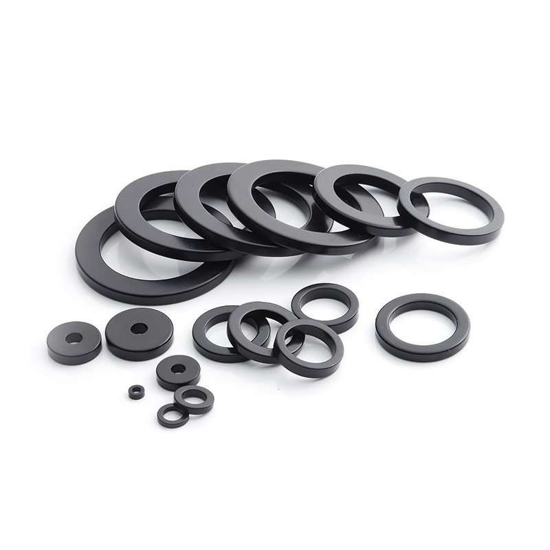
Figure 3. Real coated ring magnets: coating and geometry must remain compatible with the intended gap and mounting detail.
Use a representative sample review
A sample is most useful when checked in a representative arrangement. Confirm the actual fit, locating method, orientation and working position relative to the mating component. Where rotation, bonding or a retainer is part of production, include that condition. Record the drawing revision, sample identification and the agreed acceptance result before release.
What to include in the request
Include in the request | Why it helps |
Assembly drawing or section | Shows the shaft, hub, sensor or mating parts and makes the ring location clear. |
Finished ring dimensions | Defines inner diameter, outer diameter, thickness and any critical surface or edge requirement. |
Material and magnetic requirement | States the requested grade or performance target, magnetization direction and any required pole reference. |
Environment and process | Allows coating, temperature and assembly conditions to be reviewed with the product function. |
Sample and acceptance plan | Sets out the representative fit or functional test, quantity, records and approval step before volume production. |
Conclusion
A neodymium ring magnet for a shaft assembly should be specified as part of the complete mounting and working arrangement. Define the finished fit, functional reference, magnetization, surrounding gap and validation method together. This gives the supplier a clearer basis for review and gives the project team a more reliable sample approval before a production release.