
Neodymium Magnet Tolerances: A Practical Guide to Dimensions, Plating and Inspection
A magnet can meet the correct grade and still fail in an assembly if a critical dimension, hole, coating or magnetic orientation is not specified clearly. This guide explains how to write practical tolerance and inspection requirements for custom neodymium magnets.
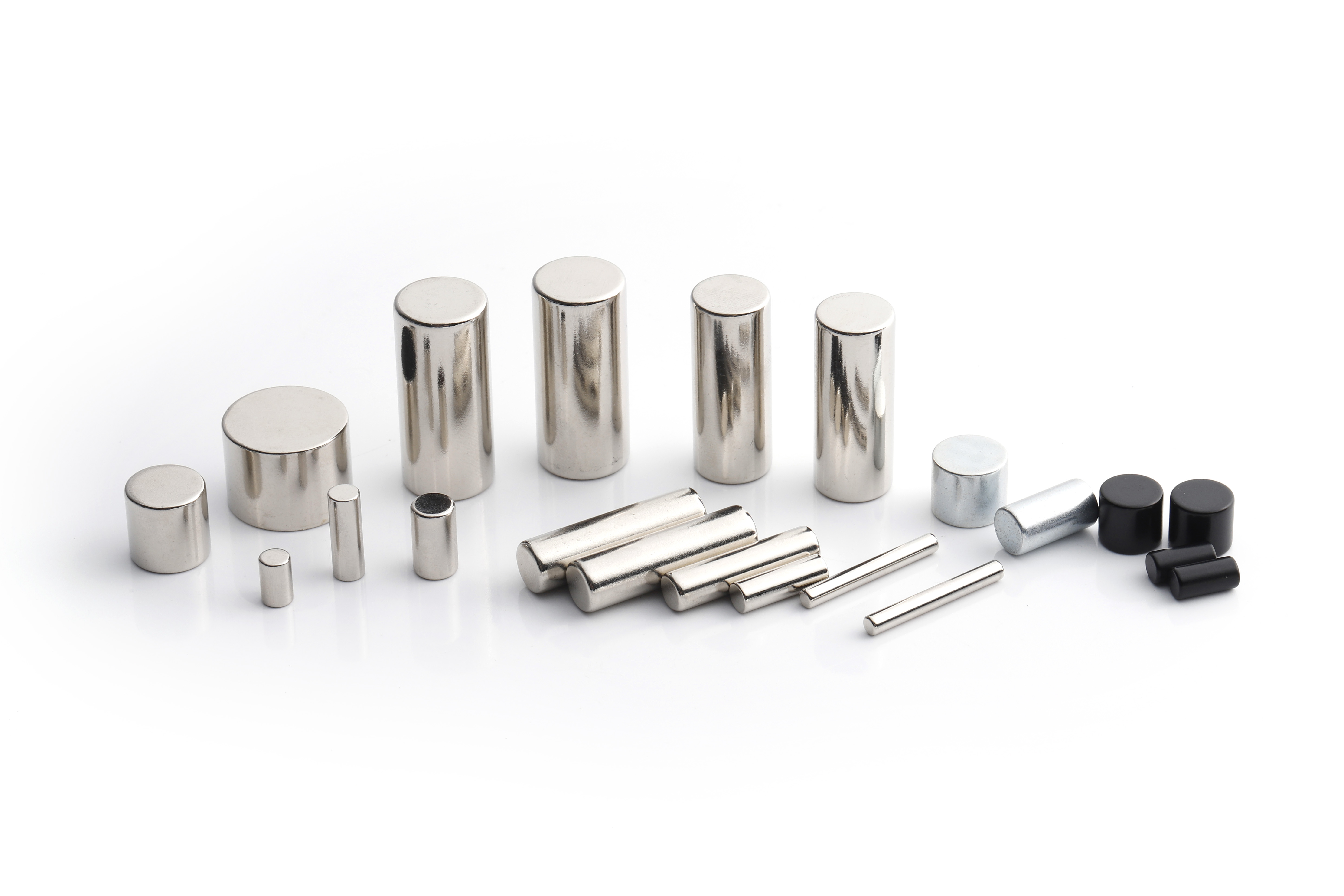
Figure 1. Real nickel-plated and black cylindrical neodymium magnets in a range of sizes.
Why nominal size is not enough
A drawing that says “disc magnet, 20 × 5 mm” identifies the basic shape, but it does not define how much variation the assembly can accept. That missing information can affect a press fit, an adhesive bond line, a rotor air gap or a multi-part magnetic array.
The practical goal is not to make every feature as tight as possible. The goal is to control the features that affect function, while allowing a manufacturable and cost-effective specification for the rest.
Start with the functional requirement
Before assigning a tolerance, identify what the magnet must do in the finished product. A cosmetic disc in a retail pack and a curved magnet bonded into a motor rotor do not need the same controls. Record the mating part, assembly process, operating temperature and any functional air gap.
Application feature | Tolerance question to answer |
Press-fit diameter | What diameter range allows assembly without cracking, loosening or excessive insertion force? |
Bonded magnet thickness | What finished thickness preserves the adhesive bond line and the required magnetic gap? |
Ring or hole diameter | What clearance is needed for the shaft, screw or locating feature? |
Array position | Which datum controls magnet location and polarity orientation relative to neighboring parts? |
Specify dimensions from clear reference surfaces
Use a dimensioned drawing or a clear CAD file whenever possible. Define the overall diameter, length, thickness, hole size, chamfer, radius and any non-standard profile. For blocks and arcs, identify the surfaces that are functionally important and use datums where position or perpendicularity matters.
For simple disc or cylinder magnets, the most common controls are diameter and thickness. For rings, both outer diameter and inner diameter should be defined independently. For custom shapes, include enough views to remove ambiguity about curved surfaces, cutouts and edges.
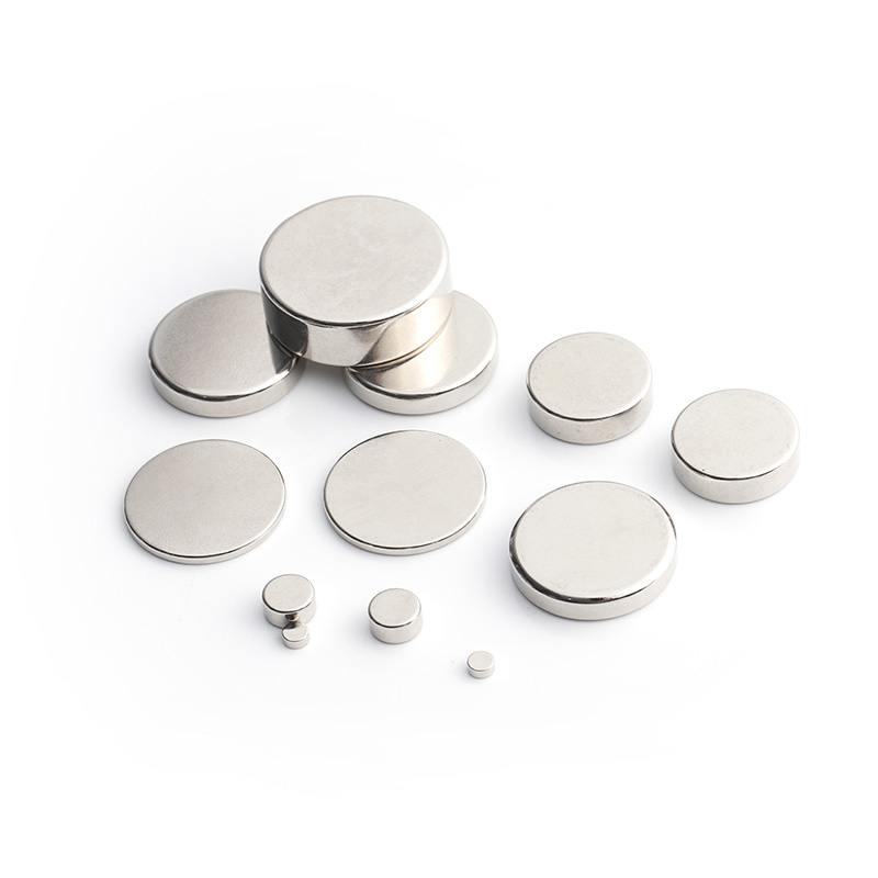
Figure 2. Real nickel-plated disc magnets showing the diameter and thickness features commonly controlled in inspection.
Account for coating in the finished-part requirement
Nickel, zinc, epoxy and other finishes change the final surface. If fit, electrical contact or surface appearance matters, state whether the drawing dimensions apply before coating or after coating. For an assembly-facing dimension, the finished coated dimension is usually the useful acceptance basis.
Also state the required coating type and any visual expectation, such as uniform coverage on visible surfaces. A coating requirement should not be used as a substitute for a dimensional requirement: both need to be stated when both matter.
Match inspection to the feature
Inspection is most useful when the measurement method fits the feature and the agreed tolerance. Calipers may be suitable for many external dimensions. Small holes, arc geometry, flatness, coating thickness or tight positional requirements may need a more appropriate gauge, fixture or measurement plan.
What to confirm | Practical inspection note |
Dimensions | List critical dimensions and their finished-part tolerance; identify any dimensions to be measured after coating. |
Appearance | Define acceptable edge condition, chips, cracks, plating coverage and cosmetic limits relevant to the application. |
Magnetic performance | State grade, magnetization direction and the agreed performance measure or test method when it is critical. |
Sampling | Agree whether first article approval, batch sampling, measurement records or retained samples are required. |
Do not over-tolerance every feature
Very tight requirements can increase processing time, inspection effort and scrap risk. Place tight tolerances only on the dimensions that drive fit, magnetic gap, location or appearance. Use a practical general tolerance for other non-critical features, and discuss any unusually tight requirement before quotation.
A useful RFQ checklist for custom magnets
Drawing or CAD file with nominal dimensions, units and revision level.
Tolerance values for critical dimensions, plus the measurement basis where coating affects the result.
Magnet material grade, magnetization direction and required pole pattern.
Coating type, color or finish requirement, and any application exposure that matters.
Acceptance criteria for appearance, dimensional inspection and magnetic performance.
Quantity, sample requirement, packaging preference and destination market requirements.
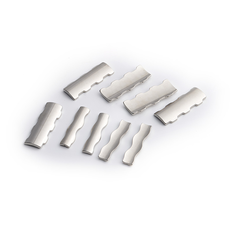
Figure 3. Real custom arc magnets, where profile geometry and locating dimensions should be specified clearly.
Example: turn a vague request into an inspectable specification
Instead of: “Please quote 5,000 strong ring magnets.”
Use: “Please quote 5,000 nickel-plated NdFeB ring magnets. Provide the drawing revision shown. Confirm finished outer diameter, inner diameter and thickness against the listed tolerances; dimensions are to be verified after coating. Axial magnetization is required. Submit first-article measurements and sample approval before mass production.”
This request gives the supplier a clear basis for quotation and gives both sides an inspection record that can be checked before volume production.
Conclusion
A well-specified neodymium magnet is easier to quote, easier to inspect and less likely to create assembly issues. Start with the function, control the dimensions that matter, make the coating basis explicit and agree how acceptance will be verified. If you have a drawing or application requirement, Xilai Technology can help review the practical magnet specification before sampling.